Longitudinal Rebar Dialog Box
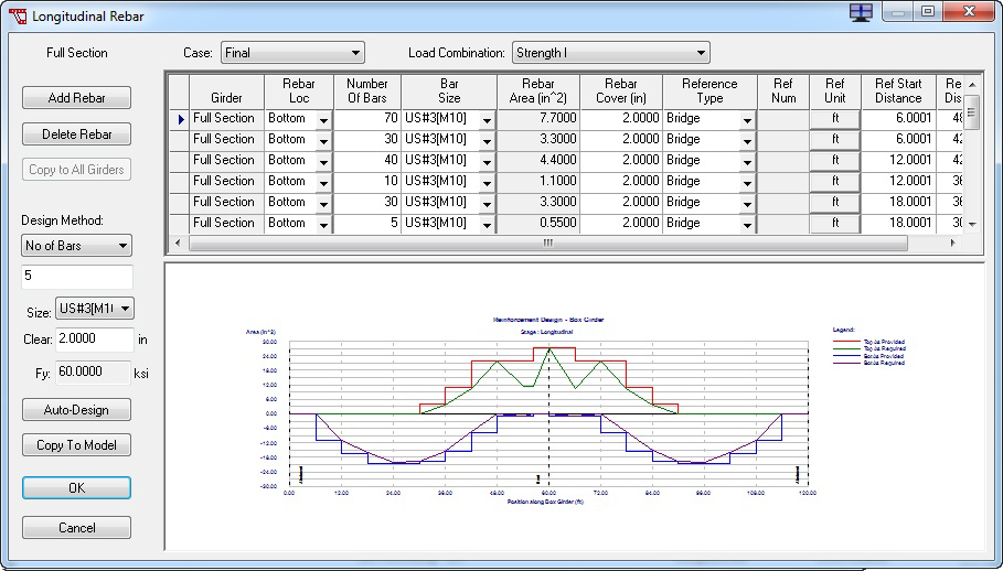
This dialog box assists you in designing a rebar layout that satisfies design requirements. To open this dialog box, click the Rebar button on the Design tab. The reinforcement requirements displayed are estimated based on the design parameters specified. To ensure that the rebar layout developed satisfies all specification requirements the user must re-run the analysis after copying the rebar design to the model and verify the design by viewing the Design Results. The user must review all defined load combinations to determine the controlling load combination to be used for design.
Adding Rebar Rows
- Select the girder section you want to modify from the drop-down list located in the Girder field.
- In the grid, select the rebar row you want to add to by clicking anywhere in its row. A blue arrow displays on the left side of the grid to mark the selection.
- Click the Add Rebar button. This adds a new rebar row after the selected row.
- Enter the rebar row values in the grid. A definition for each parameter is available below.
Copying Rebar Row Values to All Girders
In many cases, several similar rebar exist in all girders. The Copy to All Girders command is used to create a duplicate of the selected rebar in every girder to simplify the definition of similar rebar.
- Select the girder section you want to modify from the drop-down list located in the Girder field.
- In the grid, select the rebar row you want to copy. A blue arrow displays on the left side of the grid to mark the selection.
- Click the Copy to All Girders button to copy the selected row to every girder.
Grid Definitions

| Setting | Description |
|---|---|
| Girder | The girder to which the rebar applies. |
| Setting | Description | ||||||||||
|---|---|---|---|---|---|---|---|---|---|---|---|
| Rebar Loc | From the drop-down list, select whether the rebar is located on the top or bottom of the girder. This specification is used to identify rebar to be considered for positive and negative moment capacity calculations. "Bottom" rebar will be considered for positive moment capacity and "Top" rebar will be considered for negative moment capacity. | ||||||||||
| Number of Bars | Enter the number of bars needed. | ||||||||||
| Bar Size | Select the bar size from the drop-down list. The bar size name refers to a rebar material definition loaded from the Rebar Library. Rebar material definitions include specification of: unit type, yield stress (fy), ultimate stress (fu), modulus of elasticity, deformed diameter, and area. The Rebar Library can be found under the Libraries menu. Rebar material definitions must be added and deleted from the Rebar Library. An additional rebar size "unknown" is provided. Use the "unknown" size to enter the rebar area directly. | ||||||||||
| Rebar Area | Displays the total area of rebar for this row if a rebar size is used. Enter the total rebar row area for an "unknown" size. | ||||||||||
| Rebar Cover | Enter the clear cover for this rebar row | ||||||||||
| Reference Type | Select the reference type from the drop-down list.
|
||||||||||
| Ref Num | Reference number when specifying locations by Span or Support. This field will be disabled for the Bridge and Continuous location methods. | ||||||||||
| Ref Unit | Click to define the starting and ending rebar locations as either a percentage or as a distance in the current units. | ||||||||||
| Ref Start Distance | Enter the rebar starting location. | ||||||||||
| Ref End Distance | Enter the rebar ending location. |
Technical Discussion
| Setting | Description |
|---|---|
| Number of Bars | rebar patterns are based upon groups of bars that are divisible by the number of bars specified. Using this method the length of each rebar row is varied to generate a group satisfying the grouping requirements. |
| Bar Length | rebar patterns are based on bar length changes. Using this method the number of bars in the group is varied so that the cut-off length of the bar varies as specified by bar length. |
After the user has designed a reinforcement layout the layout is copied to the Model tab and an analysis is performed. The design is then confirmed by reviewing the Design Results.
Note that the estimation of the required area of reinforcement is based upon all rebar being located at the clearance specified in the design dialog. The user can modify the clearance for each bar group which will not have an effect on the required area of reinforcement. When providing layered reinforcement (i.e. rows of rebar with different clearances) use auto-design to determine the bars using one clearance then copy these bars to the Model tab. Revise the rebar size and clearance for the second layer of rebar. Click the Include Model Rebar check box and re-run the Auto-Design which will use the revised bar size and clearance to produce the second rebar layer.